In the last issue, we mainly introduced the creation of UDS diagnostic module and TSMaster basic diagnostic configuration. Many customers expressed that they are not satisfied yet. Therefore, we will continue to bring you the "TSMaster's CAN UDS Diagnostic Operation Guide (Next)", which brings you the functions of UDS on CAN/CAN FD and the detailed operation.
Keywords in this paper: UDS, BootLoader, automatic diagnostic process, diagnostic system variables
Table of Contents for this article
TSMaster Diagnostic Console
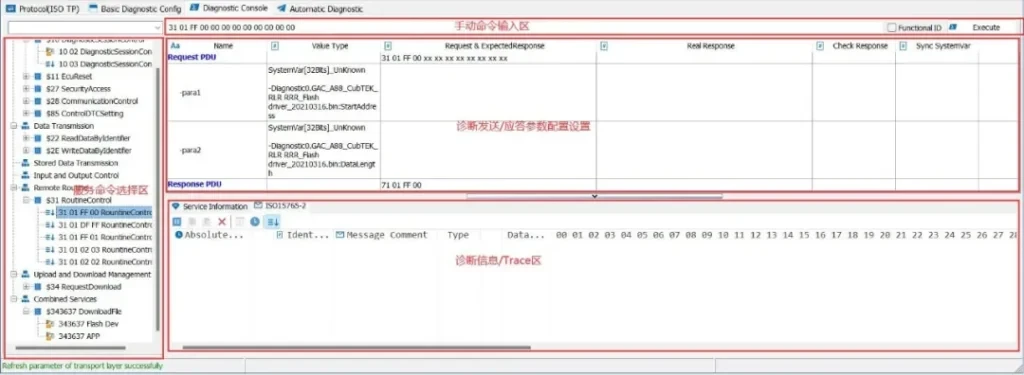
The Diagnostic Console serves as a diagnostic command debugger that allows the user to select each individual service command, edit the send service message and receive service message, and perform test verification. It mainly contains four working areas, which are Service Command Selection Area, Manual Command Input Area, Diagnostic Command Send/Answer Area and Diagnostic Information Area, as shown in Figure 4-1.
Figure 4-1 Console Work Partition
1.Service command selection area
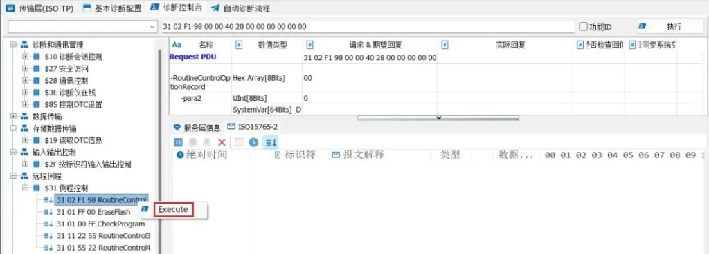
The Service Command Selection Area is a list of executable services generated based on the base configuration or loading the ODX/PDX diagnostic database. You can double-click to execute the selected service or right-click to select to execute the service, as shown in Figure 4-2.
Figure 4-2 Service Command Selection Area
2.Manual Command Entry Area
During the test, if you want to send any diagnostic command, you can enter any message you want to send in the manual command input area. After entering the diagnostic message, click the Execute button on the right to finish sending the diagnostic message. In order to increase the flexibility of the test, you can also select whether to send the diagnostic request message by physical address or by function ID through the selection box. As shown in Figure 4-3.
Figure 4-3 Manual Command Input Area
3.Diagnostic Command Send/Answer Area
In this area, the user can edit the Send Data Segment as well as the Expected Received Data Segment to initiate execution to verify that the diagnostic response of the ECU under test meets the actual requirements and synchronizes the diagnostic system variables, as shown in Figure 4-4.
Figure 4-4 Diagnostic Command Send/Answer Area
4.Diagnostic Information Area
This area is divided into the Service Layer Information and ISO15765-2 Data Flow areas, where the Service Layer Information displays the current step-by-step flow and response information in the Diagnostic Module. As shown in Figure 4-5.
Figure 4-5 Service Layer Information
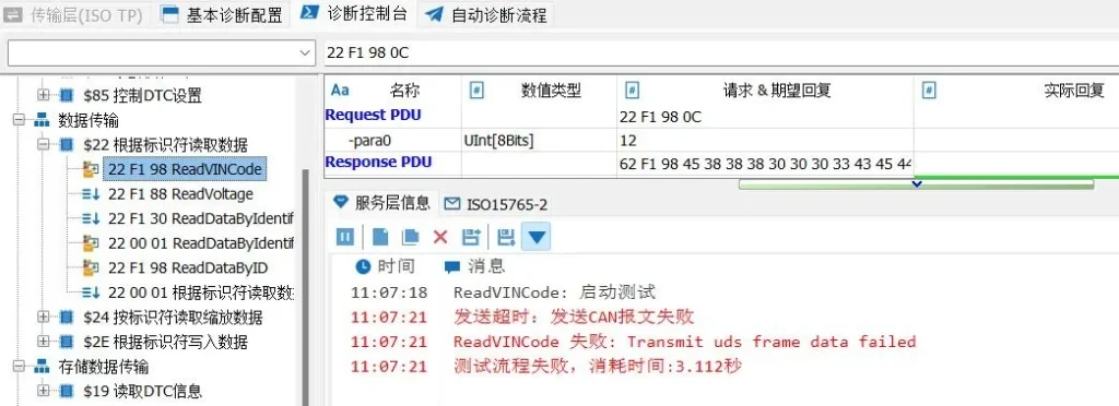
When the diagnostic service does not get a positive response or no response, the error message and so on. As in Figure 4-6:
Figure 4-6 Service Layer Message Negative Response Prompt
ISO15765-2 data flow area for displaying detailed service layer message information from the diagnostic module. Combined with the diagnostic database configured earlier, the raw message data can also be parsed into physical signals and other presentations. Taking the 22 service as an example, you can view the parameter data after parsing at the diagnostic service layer, as in Figure 4-7.
Figure 4-7 ISO15765-2 Data Flow Area
TSMaster Automated Diagnostic Processes and Registered System Variables
1.Diagnostic process creation and management
TSMaster's automated diagnostic process is not only for a specific application, but also for the whole project to manage the diagnostic process. Users can configure test diagnostic process groups according to the needs of the complete project, and each group can contain multiple different diagnostic processes, with specific diagnostic steps in one diagnostic process.
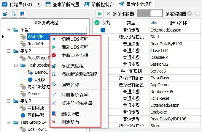
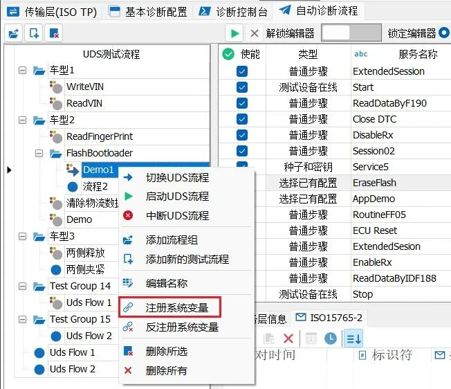
Right-click in the UDS Process Management column to expand the Process Use Case Management action menu, as shown in Figure 5-1:
Figure 5-1 Process Use Case Management Operation Menu
The operation menu contains the following operations from top to bottom:
[1] Switching UDS Processes: Switch to the current UDS process node. Double-click the node, you can also achieve the effect of switching to the process node. After switching to the node, the node icon and background color are blue, and the node process on the right expands to show the detailed diagnostic steps included in the UDS process. Figure 5-2.
Figure 5-2 Switching UDS Flow
[2] Start UDS Process: Starts the diagnostic process for this node. After clicking this option, the diagnostic module automatically executes the diagnostic steps from top to bottom according to the configuration on the right. [3] Interrupt UDS process: Clicking on this node interrupts the diagnostic process step being executed. [4] Add process group: Add a new diagnostic process group, such as Test Group1. For example, add Test Group1. diagnostic process use cases can be added under the diagnostic group, which itself does not contain diagnostic steps. [5] Add a new test process: A new diagnostic process use case is added, and detailed diagnostic steps can be added under the diagnostic process use case. [6] Programming name: Select a process group or process use case, right click and select Edit name to edit the name of the node. [7] Registering system variables: Select a diagnostic process use case and register it as a system variable. [8] Anti-registration of system variables: Check the diagnostic process use cases that have been registered as system variables and unregister the system variables. [9] Delete Selected: Deletes the selected node. [10] Delete All: Clear all nodes.
2.Configure an automated diagnostic process
TSMaster automates diagnostic processes, allows you to quickly configure multiple diagnostic processes and set up loops and register system variables for external calls, etc., as described in detail below.
2.1 Introduction to the Automatic Diagnostics Toolbar
The Diagnostic Process Configuration toolbar is shown in Figure 5-3:
Figure 5-3 Diagnostic Process Configuration Toolbar
The icons are in order from left to right:
[1] Add a new diagnostic process group. [2] New diagnostic process use cases have been added. [3] Delete the selected diagnostic process group/use case. [4] Start the configured diagnostic process. [5] Diagnostic process being run by the terminal. [6] Lock/unlock the process configuration area. If this area is locked, it becomes uneditable in the diagnostic process area. [7] All-or-nothing diagnostic process. [8] The number of cycle runs to enable the setting. [9] The actual number of runs is displayed.
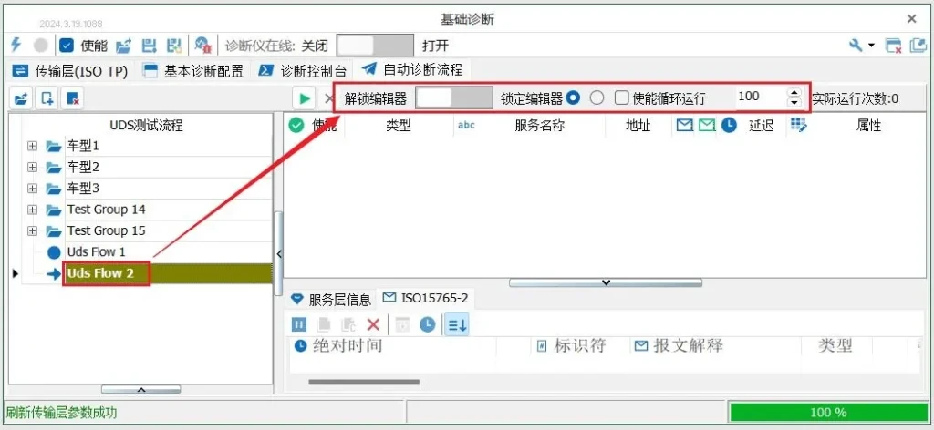
2.2 Automated Diagnostic Process Configuration Steps
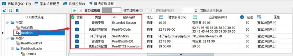
In the UDS test process area, right-click Create to create a new UDS process, double-click the process to enter, unlock the logician, and you can set the number of times this process can be run in a loop, the default is not to enable the loop. As in Figure 5-4.
Figure 5-4 Creating a New UDS Process
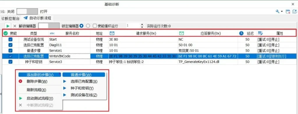
Then right-click in the Logic Area to add steps or delete steps and further parse the functions in the Admin Bar. As shown in Figure 5-5.
Figure 5-5 Adding and Managing Diagnostic Steps
[1] Select a diagnostic process node in the left management column. [2] Add, delete, and edit diagnostic steps in the edit area on the right. [3] After adding a step, select that step type. [4] Edit the step name. [5] Select the type of address for this step, physical or functional. [6] Configure detailed diagnostic request packets. [7] Configure detailed diagnostic answer packets. [8] Configure the wait time between steps after the end of this step. [9] Configure the error handling method for errors occurring in this step.
2.3 Types of diagnostic steps
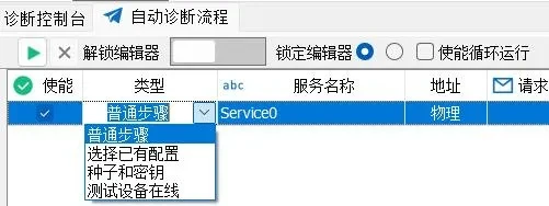
In order to increase the flexibility of diagnostic configuration in the test steps, 4 types are designed for selection, which mainly contain: Normal Step, Select Existing Configuration, Seed and Key, and Tester Online. These 4 types basically cover all the mainstream diagnostic process requirements in the market, and the characteristics of each type are described in detail below. As shown in Figure 5-6.
Figure 5-6 Types of Diagnostic Steps
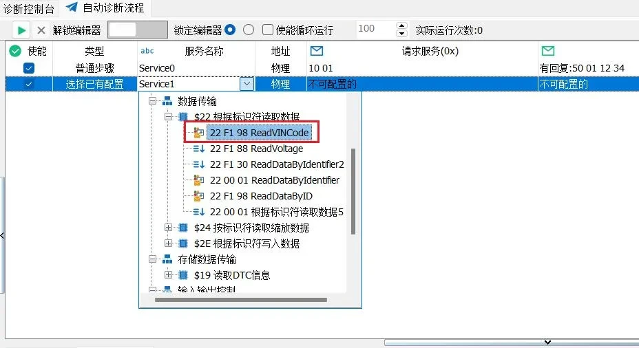
[1] Ordinary steps: Mainly used for some simple occasions where both the request data and the answer data are straightforward. Directly fill in the request data you want to send in the request service, and fill in the expected reply message in the reply service, for example, the service request data is [10 01], and the service reply data is [50 01 12 34]. As in Figure 5-7, if some services do not require a response, you can not set up a reply.
Figure 5-7 Common Step Types
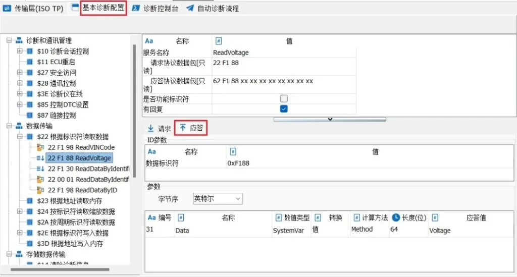
[2] Select existing configuration: This configuration is designed to allow users to select the diagnostic services that have already been configured in the basic diagnostic settings, and this is the most recommended configuration method for TSMaster. This is the most recommended way to configure TSMaster. The process of selecting the existing configuration is shown in Figure 5-8.
Figure 5-8 Selecting an Existing Configuration
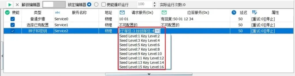
[3] Seed and Key: Seed and key only need to select the seed level and key level parameters, and the decrypted DLL is directly associated to the seed and key DLL loaded by the transport layer parameter configuration, as shown in Figure 5-9:
Figure 5-9 Seeds and Keys
In this regard, it is necessary to configure the parameter configuration of the transport layer first, both in the Diagnostic Console module and in the Automatic Diagnostic Process module.
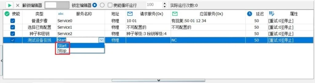
[4] Tester Online: To support more flexible testing needs, the automation process step provides the option to turn the tester online on and off with a command, as well as configure the data for that command and the cycle interval:
△ Whether to start/stop the command, as shown in Figure 5-10:
Figure 5-10 Start/Stop Tester Online Commands
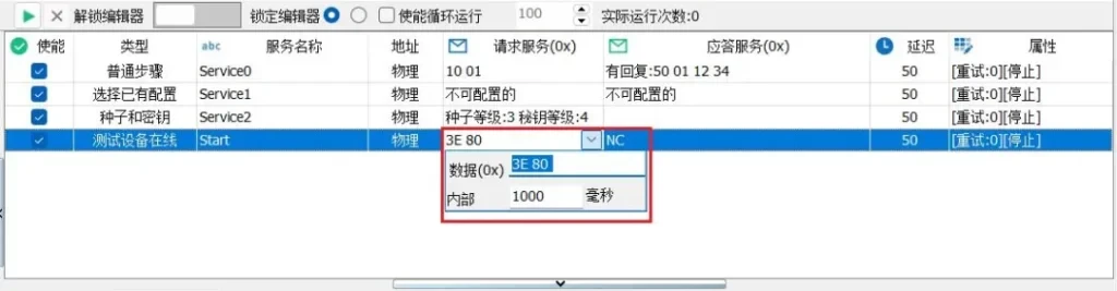
△ Configure the data for the commands for which the tester is online and the cycle intervals, as in 5-11:
Figure 5-11 Commands to Configure the Tester Online
2.4 Step intervals
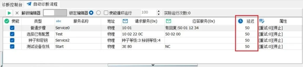
The delay between steps of the Diagnostic Flow module can be set in ms, as shown in Figure 5-12:
Figure 5-12 Commands to Configure the Tester Online
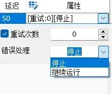
2.5 Properties
In the properties, you can set the response to an error and whether this instruction stops or continues to run, as shown in Figure 5-13:
Figure 5-13 Properties
In TSMaster's subsequent product planning, allowing jumps to specified processes (e.g., to an erase process) after a response error further increases the flexibility of the Autorun process module.
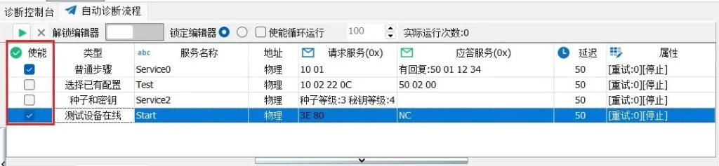
2.6 Enabling step/position adjustment
For the diagnostic process steps that have been configured, users check the diagnostic steps they want to perform according to the selection box on the left. As shown in Figure 5-14.
Adjustment of Execution Order: Whether it is a test case group, a test case or a specific step in a test case, when the user wants to adjust the execution order among them, he can directly drag and drop the corresponding test case to the corresponding position.
Figure 5-14 Diagnostic Process Step Enable
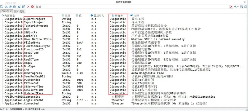
3.Endogenous system variables for diagnostic modules
After adding a new basic diagnostic module to TSMaster, the System Variable Manager will automatically generate a system variable whose owner is the diagnostic module Diagnostic, and you can configure the corresponding parameters by modifying the system variable. As in Figure 5-15.
Figure 5-15 Diagnostic Module System Variables
3.1 Diagnostic service generic system variables
Diagnostic endogenous generic system variables are included:
Export Project ExportProject: Used to export a diagnostic project.
Import Project ImportProject: Used to import an existing diagnostic project.
Diagnostic Instrument Online TesterIsPresent: Whether or not the Diagnostic Instrument Online command is initiated.
DLC: Maximum DLC value for FD frames, this parameter is only valid in FD mode.
Minimum Frame Interval for Receiving Consecutive Frames STMin (R): user-defined STMin parameter for the receiver in ms. If set to 0, it means that receiving at the shortest event interval is supported.
Minimum frame interval for sending consecutive frames STMin (T): user-defined parameter for STMin at the transmitter, in ms.
User Define STMin: if or not manually define the minimum frame interval of consecutive frames, in ms.
Fill Byte FiledByte: send diagnostic frame fill byte.
Functional ID Type FunctionalIDType: type of Transport Layer Functional ID, 0 is standard frame, 1 is extended frame.
FunctionalID: Transport layer functional ID.
Response ID Type ResIDType: type of Transport Layer Response ID, 0 is standard frame, 1 is extended frame.
Response ID (ResID): Transport layer response ID.
Request ID Type ReqIDType: type of Transport Layer Request ID, 0 is standard frame, 1 is extended frame.
Request ID (ReqID): Transport layer request ID.
BusType: Sets the bus type: 0 for CAN bus; 1 for CAN FD bus; 2 for LIN bus; 3 for DOIP (Ethernet-based diagnostics).
Channel Chn: Set the channel parameter of the diagnostic module, such as 0 for channel 1, 1 for channel 2.
Automation Process Progress UDSProgress: real-time progress of the automated diagnostic process, this variable is used to get the running status of the automated diagnostic process.
Secure Access to Seed and Key SeedAndKeyDLL: Set the absolute path to the Seed&Key DLL, be careful with escaped characters when using it.
P2 Extended Time P2Extended: Sets the P2 extended time.
P2 Extended Time P2TimeOut: Sets the P2 timeout time.
S3 Server Time S3ServerTime: Sets the S3 server time.
S3 Client Time S3ClientTime: Sets the S3 client time.
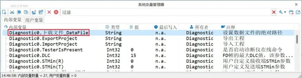
3.2 Diagnostic service-specific system variables
After adding a new service to the Composite Diagnostic Service of the Basic Diagnostic Configuration, the System Variable Manager will also generate the corresponding system variable: service_name_DataFile, which is the absolute path of the download file, and you can modify this variable to control the loading and switching of the download file. This variable is the absolute path to the download file, so you can modify it to control the loading and switching of the download file.
Figure 5-16 Download File Path System Variables
In addition, when the download file is loaded, the system variable controller generates the per-block checksum, and the total checksum, the first address and length of the download file according to the selected checksum algorithm. If the conforming diagnostic service has been added, the download file is loaded and the download file-related variables are associated with the basic diagnostic service, these associated variables will be changed at the same time as the download file is replaced with minimal Project modification to realize the flexible switching of files.
3.3 Registered system variables for automated diagnostic processes
Diagnostic services can be flexibly configured in the Diagnostic Console as needed. After these diagnostic services are configured, the user needs to double-click in the Diagnostic Console to start the diagnostic service.
If the user wants to start the diagnostic process command in the Panel interface or in the program, the steps are as follows:
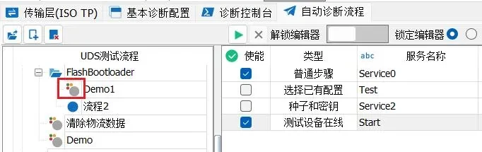
[1] First, in the Diagnostic Basic Diagnostic Config form, select the target service, and then right-click menu to register the diagnostic service as a system variable, as shown in Figure 5-17:
Figure 5-17 Diagnostic Service Registered as a System Variable
After the registration is completed, the icon of the process has 3 extra small colored circles, indicating that it becomes a service of a registered system variable, and the unregistered process is a blue circle, as shown in Figure 5-18:
Figure 5-18 Changes in Icons Registered as System Variables
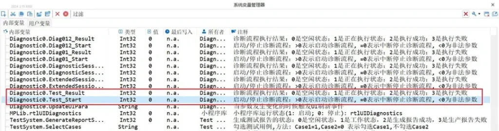
[2] After the registration is completed, you can see the generation of system variables _Start and _Result in the System Variable Manager, as shown in Figure 5-19.
Figure 5-19 Variables Registered as System Variables
where the value of _Start is assigned: ● 0 is idle. ● 1 is in the execution state. ● 2 is executed successfully. ● 3 is an execution failure.
The numerical result of _Result is: ● >0 means start diagnostic process ● =0 Indicates an interrupt to stop the diagnostic process ● <0 is an illegal parameter.
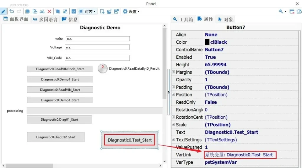
[3] Add the button button control in the Panel Panel and associate the generated system variable process name _Start, and set the button press event to 1, as shown in Figure 5-20.
Figure 5-20 Panel Button Control Associated System Variables
[4] Run the program, click the test button of Panel, assign the value 1 to the process name _Start, and the diagnostic module executes the corresponding diagnostic process to realize automatic running of the diagnostic process.
Diagnosis of typical applications
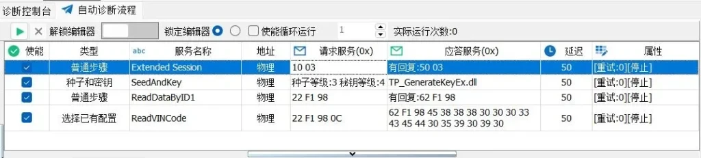
1. Read the vehicle VIN code
As follows, through the automatic diagnostic process, quickly configure to read the vehicle VIN code, one-key execution and ECU interaction, and parse the parameters of reading and adding the VIN code, the diagnostic process is as follows, such as Figure 6-1.
Figure 6-1 System Variables Associated with Panel Button Controls
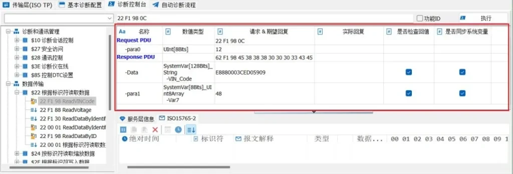
One of the service commands is parsed as follows: [1] Switch to the extended session. [2] seedkey Get permission. [3] Use the normal read command to read the VIN code returned by the vehicle. [4] Or use a previously configured command to read the VIN code, this way with data parsing.
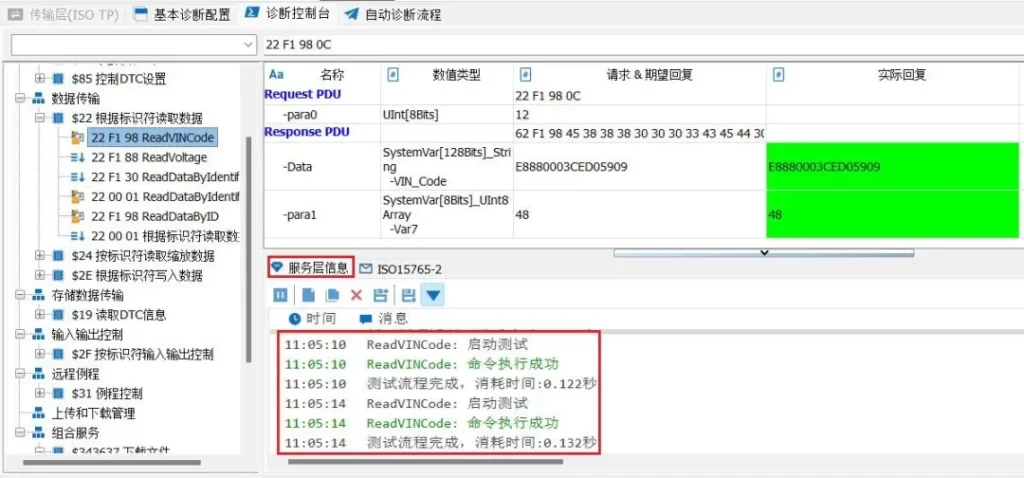
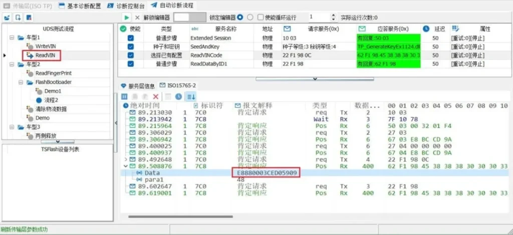
The response is executed, and the VIN code of the ECU is read normally, meanwhile, the step of selecting the existing configuration can read the VIN code "E8880003CED05909" directly because of the corresponding parsing information. As in Figure 6-2.
Figure 6-2 Reading VIN Code
2Flash Bootloader Flow
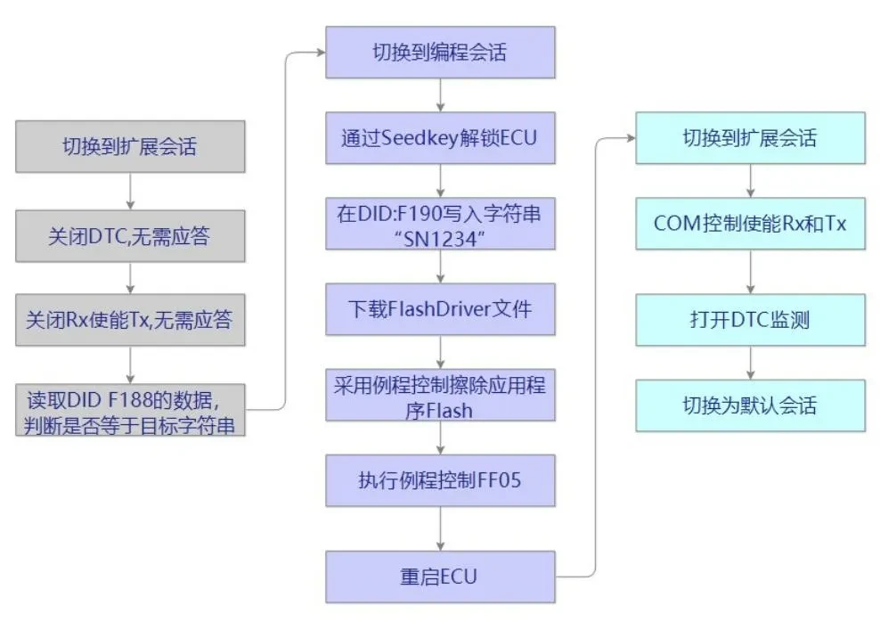
In this article, a simple bootloader flow is designed to illustrate how to configure a Flash bootloader flow based on the TSMaster diagnostic module.
2.1 Flash Bootloader Flow
Firstly, design the FashBootloader flow, which can be adjusted according to the actual design specifications of different ECUs, and is usually divided into three phases, which are the pre-programming phase (gray), the main programming phase (purple), and the post-programming phase (blue), as shown in Figure 6-3.
Figure 6-3 Designing the FashBootloader Flow
2.2 Configuring the Flashing Routine
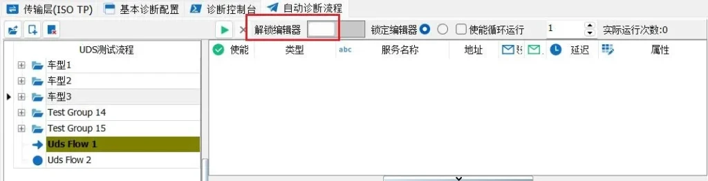
△ Pre-programming phase: 【1】First create the UDS process: note that switch the editor to unlocked state, otherwise you can not add new process steps. As in Figure 6-4.
Figure 6-4 Unlocking the Editor
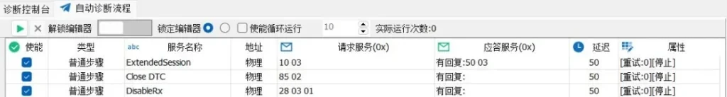
[2] For the commands shown in the flowchart such as switching extended session, closing DTC, closing receive control, etc., it is sufficient to directly configure the commands of the ordinary step type. As in Figure 6-5.
Figure 6-5 Switching Extended Sessions, Turning Off DTC, and Receiving
[3] Based on reading the data at location ID: F188 and determining if the data is equal to than SN123456. If it is, then the part number is judged to match and proceed to the next step, otherwise exit the process.
Mode 1: Use the normal step configuration form, as shown in Figure 6-6:
Figure 6-6 Ordinary Steps to Read DID F188 Part Number
Way 2: Configure it in BasicConfig and then use it in the process to select the existing configuration, as shown in Figure 6-7:
Figure 6-7 Selecting an Existing Configuration to Read DID F188 Part Number
△ Master Programming Phase:
[4] Switch to the programming session and enter the main programming stage, as in Figure 6-8.
Figure 6-8 Switching to a Programming Session
[5] Add the seed and key steps to unlock the ECU, as in Figure 6-9:
Figure 6-9 Seeds and Keys Step
[6] After obtaining the privilege, write the string "SN1234" at IDF190, for this fixed string, you can use the normal steps to configure directly, as shown in Figure 6-10:
Figure 6-10 Write String at IDF190
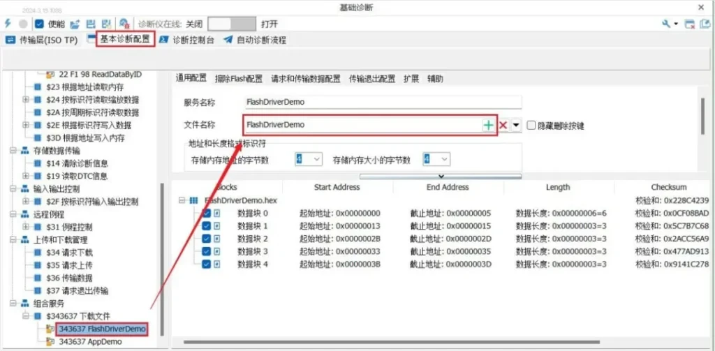
[7] Add FlashDriver/application file process. First, add FlashDriver and application files in the basic diagnostic configuration, as shown in Figure 6-11:
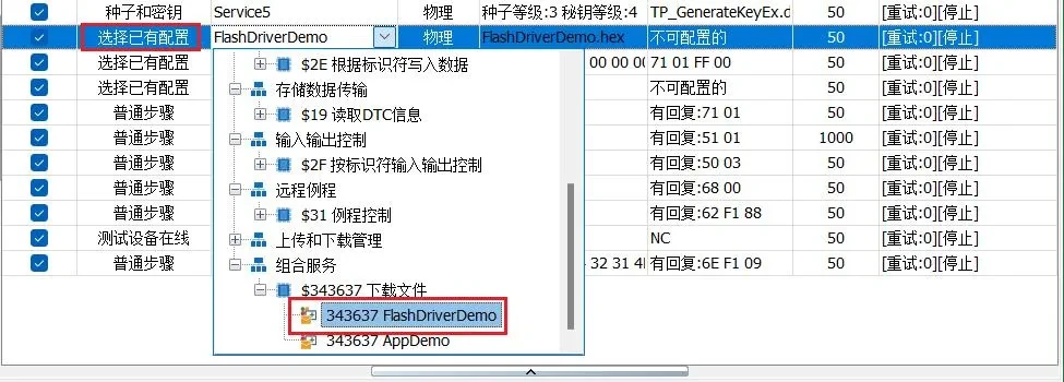
Then select the created combined download service by selecting the appropriate existing configuration in the auto-diagnostic process. As in Figure 6-12.
Figure 6-12 Selecting an Existing Combined Download Service
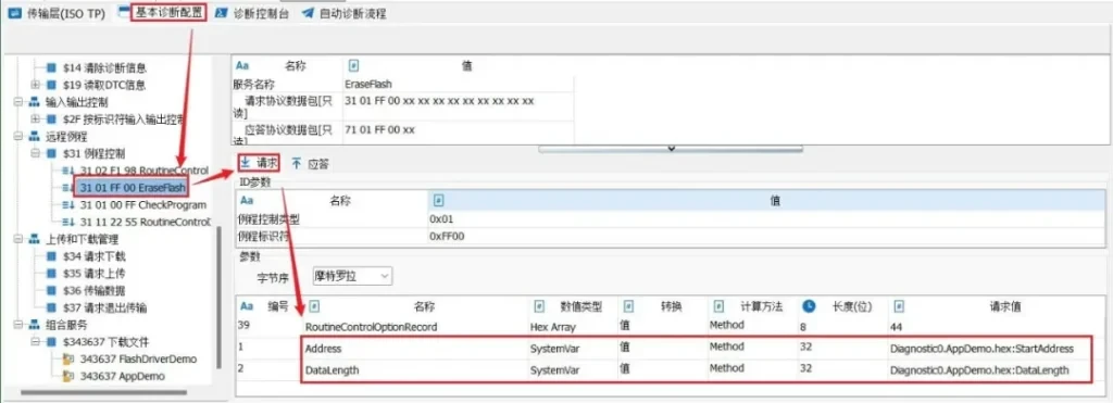
[8] Use routine control to erase Flash. Configure the post-erase instruction through diagnostic base settings, and add the request parameter by means of system variables for the start address and data length, as shown in Figure 6-13:
Figure 6-13 Diagnostic Base Configuration Erase Command
Then add to the process by selecting an existing configuration. As shown in Figure 6-14.
Figure 6-14 Routine Control Erase Flash
[9] Restart the ECU. It should be noted that the waiting time between the steps of ECUReset and restarting the diagnosis should be adjusted according to the ECU design specification, for example, set to 1000ms. as in Figure 6-15.
Figure 6-15 Restarting the ECU
△ Post-programming stage:
[10] Switch will default session, COM control, DTC control and other operations, use the workaround step to add. Such as Figure 6-16.
Figure 6-16 Post-Programming Phase
2.3 Complete process configuration and one-click operation
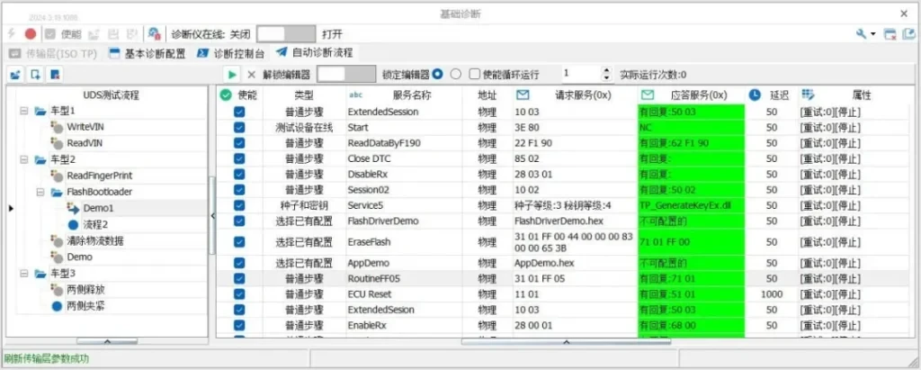
After completing the configuration, the total configuration flow is shown in Figure 6-17.
Figure 6-17 Completing the FashBootloader Configuration Flow
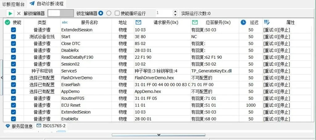
The auto-diagnostic process is executed with one touch of a button, and when each step is positively responding, it will be displayed in green, as in Figure 6-18:
Figure 6-18 Automated Diagnostic Process Performed with One Click
Based on TSMaster's diagnostic module, a zero-code approach is realized, and the development of diagnostic processes such as bootloader applications becomes a very simple and fast thing to do.
Beta version updated weekly, full version updated monthly
Installation environment
1
Windows 7 SP1 or higher, supports Win10, and WIn11.
Operating System
2
8GB
random access memory (RAM)
3
At least 550MB of free space
disk space
4
Dual-core (2-core) or higher
CPU
Please ensure that your computer meets at least these requirements in order to install and run the TSMaster software successfully. If your computer does not meet these requirements, it may cause performance problems or not run the software properly. You may want to consider upgrading your hardware if you need smoother running features.